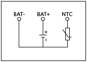
In lithium batteries, a thermistor with a negative temperature coefficient (NTC) is usually installed. The NTC thermistor can prevent the battery from being charged at too high or too low temperatures. Therefore, the battery has three connection terminals: the positive terminal (BAT+), the negative terminal (BAT-) and the connection terminal of the NTC thermistor (see Figure 1). Please note that some batteries with three connections only have ordinary resistors inside for identification. The value of the ordinary resistance will be constant and will not change with the battery temperature.
Figure 1. Most lithium batteries with three connections have an internal NTC thermistor
When using NTC thermistor, it should be connected between THM pin and ground (connected via BAT). A resistor (R7) is also connected between the THM pin and the reference voltage (VL), which creates a voltage divider. Choose the value of the resistor so that it has the same value as the NTC thermistor at a temperature of +25°C. The voltage on the THM pin at +25°C is equal to 0.5 VL. When the temperature rises or falls, the resistance of the NTC thermistor also falls or rises, and the voltage on the THM pin also falls or rises. The device will only charge when this voltage is between 0.28 VL and 0.74 VL. For contemporary NTC thermistors, this corresponds to a temperature between 0°C and 50°C. If there is no NTC thermistor available, R8 should be added, which will result in a voltage of 0.5 VL on the THM pin.
From a physical point of view, heat is a measure of the energy contained in the body due to the irregular movement of its molecules or atoms. Just as tennis balls have more energy with increasing speed, the internal energy of the body or gas increases as the temperature increases. Temperature is a variable that, along with other parameters such as mass and specific heat, describes the energy content of the body.
The basic measure of temperature is Kelvin degree. At 0 ° K (Elvin), every molecule in the body is at rest and there is no more heat. Therefore, there is no possibility of negative temperature because there is no state of lower energy.
In daily use, the usual practice is to use centigrade (formerly centigrade). Its zero point is at the freezing point of water, which can be easily reproduced in practice. Now 0 ° C is by no means the lowest temperature, because everyone knows from experience. By extending the centigrade scale to the lowest temperature at which all molecular motion stops, we reach – 273.15 degrees.
Man has the ability to measure temperature through his senses in a limited range. However, he was unable to accurately reproduce quantitative measurements. The first form of quantitative temperature measurement was developed in Florence in the early 17th century and relied on the expansion of alcohol. Scaling is based on the highest temperatures in summer and winter. A hundred years later, the Swedish astronomer Celsius replaced it with the melting and boiling points of water. This gives the thermometer the opportunity to zoom in and out at any time and reproduce the readings later.
Electrical measurement temperature
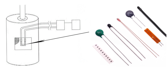
Temperature measurement is important in many applications, such as building control, food processing, and the manufacture of steel and petrochemical products. These very different applications require temperature sensors with different physical structures and usually different technologies
In industrial and commercial applications, measurement points are usually far away from indication or control points. Further processing of measurements is usually required in controllers, recorders or computers. These applications are not suitable for direct indication of thermometers because we know them from everyday use, but need to convert the temperature into another form of device, the electrical signal. In order to provide this remote electrical signal, RTD is usually used. Thermistors and thermocouples.
RTD adopts the characteristic of metal resistance changing with temperature. They are positive temperature coefficient (PTC) sensors whose resistance increases with temperature. The main metals used are platinum and nickel. The most widely used sensors are 100 ohm or 1000 ohm RTDS or platinum resistance thermometers.
RTD is the most accurate sensor for industrial applications and also provides the best long-term stability. The representative value of platinum resistance accuracy is + 0.5% of the measured temperature. After one year, there may be + 0.05 ° C change through aging. Platinum resistance thermometers have a temperature range of – 200 to 800 ° C.
Change of resistance with temperature
The conductivity of a metal depends on the mobility of the conducting electrons. If a voltage is applied to the end of the wire, the electrons move to the positive pole. Defects in the lattice interfere with this motion. They include external or missing lattice atoms, atoms at grain boundaries and between lattice positions. Since these fault locations are temperature independent, they produce a constant resistance. With the increase of temperature, the atoms in the metal lattice exhibit increased oscillations near their stationary positions, thus hindering the movement of the conducting electrons. Since the oscillation increases linearly with temperature, the resistance increase caused by the oscillation depends directly on the temperature.
Platinum has been widely accepted in industrial measurement. Its advantages include chemical stability, relatively easy fabrication (especially for wire manufacturing), the possibility of obtaining it in high purity form, and reproducible electrical properties. These characteristics make platinum resistance sensor the most widely interchangeable temperature sensor.
Thermistors are made of some metal oxides and their resistance decreases with increasing temperature. Because the resistance characteristic decreases with the increase of temperature, it is called negative temperature coefficient (NTC) sensor.
Due to the nature of the basic process, the number of conducting electrons increases exponentially with temperature; therefore, the characteristic shows a strong increase. This obvious nonlinearity is a disadvantage of NTC resistors and limits its effective temperature range to about 100 ° C. They can, of course, be linearized by automated computers. However, the accuracy and linearity can not meet the requirements of large measurement span. Their drift at alternating temperatures is also larger than that of RTD. Their use is limited to monitoring and indicating applications where the temperature does not exceed 200 ° C. In this simple application, they are actually superior to the more expensive thermocouples and RTDs, considering their low cost and the relatively simple electronic circuits required.
The basis of thermocouple is the connection between two different metals, thermistor. The voltage generated by thermocouple and RTD increases with temperature. Compared with resistance thermometers, they have a higher upper temperature limit, with a significant advantage of several thousand degrees Celsius. Their long-term stability is slightly poor (several degrees after a year), and the measurement accuracy is slightly poor (average + 0.75% of the measurement range). They are often used in ovens, furnaces, flue gas measurement and other areas where temperatures are higher than 250 ° C.
The difference between thermocouple, thermistor and RTD
Thermoelectric effect
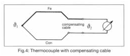
When two metals are connected together, thermoelectric voltage is produced due to the different binding energy of electrons and metal ions. The voltage depends on the metal itself and the temperature. In order for this thermal voltage to generate current, the two metals must of course be connected together at the other end to form a closed circuit. In this way, a thermal voltage is generated at the second junction. The thermoelectric effect was discovered by Seebeck in 1822. As early as 1828, Becquerel suggested the use of platinum palladium thermocouple for temperature measurement.
If there is the same temperature at both junctions, there is no current flow because the partial pressures generated at the two points cancel each other out. When the temperature at the junction is different, the voltage generated is different and the current flows. Therefore, thermocouple can only measure temperature difference.
The measuring point is a junction exposed to the measured temperature. The reference junction is a junction at a known temperature. Since the known temperature is usually lower than the measured temperature, the reference junction is usually called a cold junction. In order to calculate the actual temperature of the measuring point, the cold end temperature must be known.
Older instruments use thermostatic control junction boxes to control the cold junction temperature at known values such as 50c. Modern instruments use thin-film RTD at the cold end to determine its temperature and calculate the temperature of the measuring point.
The voltage produced by the thermoelectric effect is very small and is only a few microvolts per degree centigrade. Therefore, thermocouples are not normally used in the range of – 30 to + 50 ° C, because the difference between the reference junction temperature and the reference junction temperature is too small to produce a non-interference signal.
RTD wiring
In a resistance thermometer, the resistance varies with temperature. To evaluate the output signal, a constant current passes through it and the voltage drop across it is measured. For this voltage drop, Ohm’s law is obeyed, v = IR.
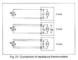
The measurement current should be as small as possible to avoid sensor heating. It can be considered that the measurement current of 1mA will not introduce any obvious error. The current produces a voltage drop of 0.1V in PT 100 at 0 ℃. This signal voltage must now be transmitted through the connecting cable to the indication point or evaluation point with minimal modification. There are four different types of connection circuits:
The difference between thermocouple, thermistor and RTD – 1
2-wire circuit
A 2-core cable is used for the connection between the thermometer and the evaluation electronics. Like any other electrical conductor, the cable has a resistance in series with a resistance thermometer. As a result, the two resistors are added together and the electronics interpret it as a temperature rise. For longer distances, the line resistance can reach several ohms and produce a significant offset in the measured value.
3-wire circuit
In order to minimize the influence of line resistance and its fluctuation with temperature, a three wire circuit is usually used. It includes running additional wires on one of the contacts of the RTD. This results in two measurement circuits, one of which is used as a reference. The 3-wire circuit can compensate the line resistance in terms of its number and temperature variation. However, all three conductors are required to have the same characteristics and to be exposed to the same temperature. This is usually applied to a sufficient extent to make 3-wire circuits the most widely used method today. No line balancing is required.
4-wire circuit
The best connection form of resistance thermometer is 4-wire circuit. Measurement depends neither on line resistance nor on temperature induced changes. No line balancing is required. The thermometer provides measurement current through a power connection. The voltage drop on the measuring line is picked up by the measuring line. If the input resistance of an electronic device is many times greater than the line resistance, the latter can be ignored. The voltage drop determined in this way is independent of the characteristics of the connecting wire. This technique is usually used only for scientific instruments that require a measurement accuracy of one hundredth.
The difference between thermocouple, thermistor and RTD – 2
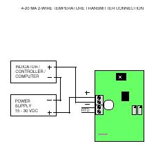
2-wire transmitter
By using a 2-wire transmitter instead of a multi wire cable, the problem of a 2-wire circuit as described above can be avoided. The transmitter converts the sensor signal into a normalized current signal of 4-20mA, which is proportional to the temperature. The power supply to the transmitter also operates through the same two connections, using a basic current of 4 mA. The 2-wire transmitter provides an additional advantage, that is, signal amplification greatly reduces the impact of external interference. There are two arrangements for positioning the transmitter. Since the distance between non amplified signals should be as short as possible, the amplifier can be directly installed on the thermometer in its terminal head. This best solution is sometimes not possible due to structural reasons or considerations that the transmitter may be difficult to reach in the event of a failure. In this case, the rail mounted transmitter is installed in the control cabinet. The advantage of improved access is that it is purchased at the cost of a longer distance that the non amplified signal must travel.
Thermistor wiring
The resistance of a thermistor is usually several orders of magnitude greater than that of any lead wire. Therefore, the effect of lead resistance on temperature readings is negligible, while thermistors are almost always connected in a 2-wire configuration.
Thermocouple wiring
Unlike RTDS and thermistors, thermocouples have positive and negative legs, so polarity must be observed. They can be connected directly to the local 2-wire transmitter and the copper wire can be returned to the receiving instrument. If the receiving instrument can accept thermocouple input directly, the same thermocouple wire or thermocouple extension wire must be used all the way back to the receiving instrument.
The great advantage of thermistor is its high sensitivity. They are mainly used for room temperature measurements up to moderate high temperatures. They are popular in research and medical applications, such as electronic medical thermometers.
Thermistor is a kind of thermistor whose resistance varies with temperature. Resistance is measured by passing a small measuring direct current (DC) through it and measuring the resulting voltage drop.
There are two basic types of thermistors, PTC and NTC:
PTC (positive temperature coefficient) devices show an increase in resistance as the temperature increases. PTC thermistor is a temperature dependent resistor made of barium titanate. It should be selected when the resistance needs to be greatly changed at a specific temperature or current level.
The NTC (negative temperature coefficient) device shows a decrease in resistance as the temperature increases. NTC thermistors are made up of semiconductors. They are made from a mixture of oxides of manganese, cobalt, copper or nickel. Their operating temperature ranges from – 150 ° C to 600 ° C. For a temperature of about 700 ℃, devices using zirconia doped with rare earth oxides can be used. NTC should be selected when it is necessary to change the resistance continuously in a wide temperature range. They have mechanical, thermal and electrical stability as well as high sensitivity.
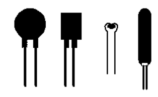
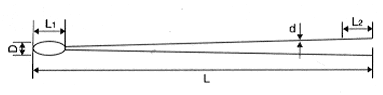
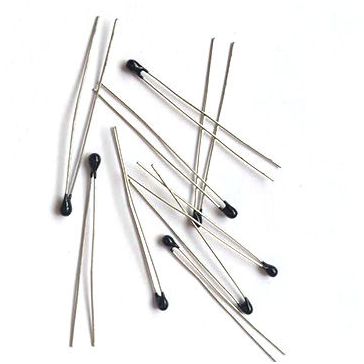
Thermistors are commercially available in various shapes: beads, discs, chips and probes. The most common form is a bead with two wires attached. The bead diameter can be about 0.5mm to 5mm.
The main advantages and disadvantages of NTC and PTC Thermistors
Small size thermistors make them very adaptable and are usually included in electronic circuits. They can be encapsulated in epoxy or glass or painted. Thermistors are simple, robust and very reliable
Temperature dependence of resistance
The resistance of CTN thermistor decreases exponentially with the increase of temperature. It is negative and nonlinear, as shown by the following relation:
Where R 0 is the nominal resistance measured at the absolute temperature t0 (usually measured at 25 ° C) and B is the constant of the specific thermistor material. The nonlinear characteristics of resistors may be undesirable, and this can be offset by using two or more thermistors in series or in parallel, packaged in a single device.
The temperature coefficient of resistance α, expressed in% / K (or% / ° C), is defined as follows:
The coefficient α of PTC thermistor is positive, while that of NTC thermistor is negative.
The Steinhart & Hart equation can be used to determine the temperature from the thermistor:
Where R is the thermistor in ohm, t is the absolute temperature, K, a, B and C are constants, which are usually provided by the manufacturer, but can be determined by calibrating at three different temperatures and solving three simultaneous equations.
This equation is very close to the actual device, but it does not always provide the required accuracy over the entire temperature range. This can be corrected by fitting the Steinhart & Hart equations over a range of narrow temperature ranges and then “stitching” them together to cover the desired range.
Advantages and disadvantages of thermistor
The great advantage of thermistors is that they can be point measured
Compared with other temperature sensors, their high sensitivity allows thermistors to operate in a small temperature range and are very accurate (usually better than 0.05 ° C and 0.1 ° C). The sensitivity of thermistor can be one order of magnitude higher than that of resistance thermometer (RTD)
The most common temperature range is 0 ° C to 100 ° C. At higher temperatures, they drift greatly
The high resistivity of thermistors eliminates the need for a four wire bridge circuit
Thermistors are very nonlinear and not robust, which limits their application
The error source is due to the self heating effect caused by excessive bias current when the thermistor is powered on to provide the output voltage signal. In order to reduce this source of error, a current suitable for measuring resistance must be used.
Due to its performance and moderate cost, thermistors are suitable for temperature measurement and control, temperature compensation, electronics, medical and many other applications.
The main parts of the dishwasher are
made of steel and plastic. The basic structure consists of steel frame
components and steel door panels. Stainless steel plate is purchased and
processed in the factory according to the required parts and shapes;
independent door and surround cabinet are purchased with coil steel plate, and
have been pre processed in several standard colors. Other small steel parts are
designed in-house but manufactured by the supplier to the manufacturer's
specifications.
The shelves for the dishes are also made
of steel, but are shipped to the factory in the form of coiled steel wires. To
coat the rack to prevent scratching the rack, immerse the rack in plastic in
the form of powdered polyvinyl chloride (PVC) or nylon.
The inner box that holds the rack and
the arm of the washing machine is called the bathtub. It is a single piece that
is injection molded in the factory (excluding the door liner). Injection
molding is accomplished by calcium reinforced polypropylene plastic granules.
This plastic is respected for its strength and inertia. That is, it does not
react with chemicals in detergents and is water and heat resistant. Many other
components, including the cutlery basket, detergent container, scrubber and
spray arm, are also molded.
The temperature
sensor made of NTC thermistor can detect the temperature in the dishwasher and
make corresponding instructions according to the temperature of each stage.
Therefore, it is easy to monitor the dishwasher and detect when the specified
temperature is reached through NTC thermistor.
High precision NTC thermistor can realize extremely accurate temperature measurement. Mf51e NTC thermistor is specially designed for electronic thermometer with higher than average accuracy. The very small size enables the thermistor to respond quickly to small changes in temperature. Mf51e can provide uncalibrated standard tolerances or can be calibrated and grouped at 37 ° C ± 0.01% based on R to achieve high interchangeability without additional calibration.
Application
Electronic thermometer
Medical equipment and patient monitoring
characteristic
Small size, fast response and light weight
Available tolerances: ± 0.5%, ± 1%, ± 2%, ± 3% and ± 5%
B value tolerance: ± 0.5%, ± 1.0% and ± 2.0%
Resistance calibration can be performed at 37 ° C ± 0.01% (see table for grouping details)
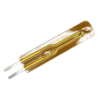
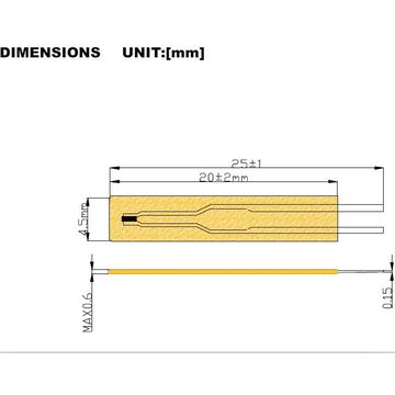
The thin-film NTC thermistor is made of a polyimide film with a thickness of only 15 microns, which is wrapped on the NTC thermistor chip. The ultra-thin packaging method makes it have a faster temperature detection effect and a higher temperature measurement speed. Fast, the speed of general equipment reflecting the thermistor chip is less than 4S. Thin-film NTC thermistors are very small in size, fun and flexible, so they are often installed in small spaces. The thin-film NTC thermistor leads are integrally formed, and the insulation does not need to be used through a sleeve to avoid lead oxidation, and has a good waterproof effect.
Product size drawing of thin film NTC thermistor:
Main features of thin film NTC thermistors:
• Insulating film packaging, fast heat sensing, high sensitivity, high resistance accuracy
• Good stability, high reliability and good insulation
• Small size, light weight, strong and durable, easy to install and automate
The main parameters of thin film NTC thermistor:
• R(25): 10k
• Tolerance: 1%, 2%, 3%, 5%, 10%
•B value (25/85): 3435
• Insulation resistance: ≥100MΩ
• Thermal time constant: ≤5s
• Heat dissipation constant: ≥3.5mw/℃
• Operating temperature range: -40°C-+ 120°C
• Model: MF55
• Packing: 1000PCS/bag
• Lead-free: RoHS compliant
Scope of application:
• Temperature measurement, temperature control, temperature compensation
•Practical applications: computers, printers, household appliances, etc.
We can provide more types of NTC thermistors and data according to your requirements.
The latest product of air purifier industry, a kind of voltage adjustable electrostatic precipitator combined with ultraviolet lamp sterilization control system for household air purifier is designed. The system uses low-power 32-bit microprocessor stm32f103rct6 as the main control chip, uses DHT11 temperature and humidity sensor, gp2y1010au0f dust sensor and TGS2600 gas sensor to detect indoor air quality. The collected data is transmitted to the single-chip microcomputer and displayed on TFTLCD. According to the received data, MCU uses the key or Bluetooth to adjust the motor wind speed, voltage and the switch of UV lamp to make the air purifier in the best working state. After debugging, the system runs stably and the effect is obvious. The sensor consists of a resistance type humidity measuring element and a temperature measuring NTC thermistor element, and is connected with a high-performance 8-bit single-chip microcomputer. Through the simple circuit connection of MCU and other microprocessors, the local humidity and temperature can be collected in real time.
Mf52ntc thermistor developed and produced by our company can be suitable for use in air purifier. In the existing customer cases, only welding the thermistor on the control main board of air purifier can effectively detect the temperature inside the purifier and ensure the safe and intelligent use of the air purifier. More air purifier NTC thermistor recommendations, please contact our sales staff, will provide professional NTC thermistor introduction and free sample testing.
The characteristics of mf52ntc thermistor are as follows
1. Low cost / high stability / small size / epoxy package / fast thermal response.
2. Thermal time constant: maximum 2 seconds, 15 seconds in a fully stirred oil bath. In the still air.
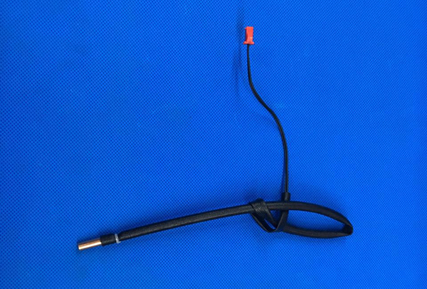
When household appliances are working, the motor rotates at a high speed and heats up quickly. A thermal protection device must be used to protect the motor. During the assembly process, the external thermal protection device must be installed for protection.
Thermal protection devices include NTC thermistors, bushings, wires, converters, controllers, signal lines, and fixing devices. After the applied NTC thermistor is covered with a silicone sleeve, a wire (Teflon wire) is used to make the thermistor and the converter form a loop; the high-temperature double-sided tape is used to close the sleeved thermistor to A layer of aluminum foil tape is attached to the outermost layer of the motor housing, and the converter is connected to the controller through a signal line.
The use environment of the motor is usually in high temperature, high humidity, acidic or alkaline for a long time, and the motor itself vibrates greatly, so it is necessary to protect the NTC thermistor, that is, put a sleeve on the thermistor. The casing is mostly silica gel or Teflon U-shaped casing. The use of silica gel casing has the advantages of shockproof and moisture-proof, low cost, easy installation, and easy forming; the use of Teflon casing has the advantages of rapid heat conduction and corrosion resistance. Double-sided high temperature resistant adhesive tape or high temperature resistant adhesive, simple operation, convenient installation and low cost when fixing thermistor. The aluminum foil tape reflects the heat radiated from the measuring part back to the thermistor, so that the temperature measurement is more accurate and the result is not distorted. Moreover, the aluminum foil tape has good adhesion, strong adhesion, and anti-aging, which makes the overall installation of the thermistor more reliable.
The NTC thermistor produced by Vsec elec has the characteristics of high reliability, high sensitivity and high precision. It can effectively and quickly perform temperature measurement and temperature control, and plays an indispensable role in the motor thermal protection device of household appliances.
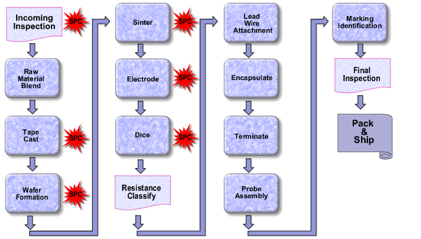
The NTC thermistor manufacturing process can be divided into: Incoming Inspection – Raw Material Blend – Tape Cast – Wafer Formation – Sinter – Electrode – Dice – Resistance Classify – Lead Wire Attachment – Encapsulate – Terminate – Probe Assembly – Marking Identification – Final Inspection – Pack & Ship.
1. Incoming Inspection
All raw materials are inspected upon receipt to verify whether their physical and electrical properties are acceptable. Assign a unique ID# and use it for batch traceability.
2. Raw Material Blend
The manufacture of NTC thermistors begins with the precise mixing of raw materials into organic binder solutions. These raw materials are powdered transition metal oxides such as manganese, nickel, cobalt and copper oxide. Other stabilizers are also added to the mixture. The oxide and binder are combined using a wet process technique called ball milling. In the ball milling process, the materials are mixed and the particle size of the oxide powder is reduced. The finished homogeneous mixture has the consistency of a thick paste. The exact composition of various metal oxides and stabilizers determines the resistance-temperature characteristics and resistivity of the fired ceramic components.
3. Tape Cast
The “slurry” is distributed on a moving plastic carrier sheet using doctor blade technology. The exact material thickness is controlled by adjusting the height of the squeegee above the plastic carrier sheet, the speed of the carrier sheet and by adjusting the slurry viscosity. The casting material is dried on a flat casting belt through a long tunnel oven at high temperature. The resulting “green” tape is malleable and easy to form. Then carry out quality inspection and analysis on the tape. The thermistor tape thickness ranges from 0.001″ to 0.100″ in a wide range, depending on the specific component specifications.
4. Wafer Formation
The tape is ready to be formed into wafers. When thin materials are needed, simply cut the tape into small squares. For thicker wafers, cut the tape into squares and stack it on top of the other. These stacked wafers are then laminated together. This allows us to produce wafers of almost the required thickness. Then, the wafer undergoes additional quality testing to ensure high uniformity and quality. Subsequently, the wafer is subjected to a binder burnout cycle. This method removes most of the organic binder from the wafer. In order to prevent adverse physical stress on the thermistor wafer, precise time/temperature control is maintained during the adhesive burning cycle.
5. Sinter
The wafer is heated to a very high temperature in an oxidizing atmosphere. At these high temperatures, the oxides react with each other and fuse together to form a spinel ceramic matrix. During the sintering process, the material is densified to a predetermined level, and the grain boundaries of the ceramic are allowed to grow. Maintain a precise temperature profile during the sintering process to avoid wafer fracture and ensure the production of finished ceramics that can produce parts with uniform electrical characteristics. After sintering, the quality of the wafer is inspected again, and the electrical and physical characteristics are recorded.
6. Electrode
Ohmic contact with ceramic wafers is obtained using thick film electrode materials. The material is usually silver, palladium silver, gold or platinum, depending on the application. The electrode material consists of a mixture of metal, glass and various solvents, and is applied to the two opposite surfaces of a wafer or chip by screen printing, spraying or brushing. The electrode material is fired on the ceramic in the thick film belt furnace, and the electrical joint and mechanical combination are formed between the ceramic and the electrode. Then check the metallized wafer and record the properties. Precise control in the electrode process ensures that the components produced from wafers will have excellent long-term reliability
7. Dice
High speed semiconductor cutting saw is used to cut the chip into small chips. The saw blade uses a diamond blade and can produce a large number of extremely uniform dies. The resulting thermistor chip can be as small as 0.010 “to 1000”. The chip size difference of a set of chip thermistor chips is actually immeasurable. A typical thermistor chip can produce thousands of thermistor chips. After cutting, clean the chip and check the dimensions and electrical characteristics. Electrical inspections include the determination of nominal resistance values for specific applications, resistance temperature characteristics, production yield, and batch acceptability. Resistance and resistance temperature characteristics are accurately measured within 0.001 ° C using precise temperature control.
8. Resistance Classify
All thermistors are tested for proper resistance values, usually 25 ° C. These chips are usually tested automatically, but they can also be tested manually based on production and specifications. The automatic chip processor is connected to a resistance test device and a computer programmed by the operator to place the chip in various memory areas dependent on its resistance value. Each automatic chip processor can test 9000 parts per hour in a very accurate way.
9. Lead Wire Attachment
In some cases, thermistors are sold in the form of chips and do not require leads, but in most cases leads are required. The thermistor chip is connected to the leads by soldering or by pressure contacts in the diode package. During the welding process, the thermistor chip is loaded on the lead frame, which depends on the spring tension of the wire to maintain the chip during the welding process. The assembly is then immersed in the molten solder pot and removed. The impregnation rate and residence time are precisely controlled to avoid excessive thermal shock to the thermistor. Special fluxes are also used to enhance the solderability without damaging the thermistor chip. The solder adheres to the chip electrodes and leads to provide a firm wire to chip bond. For the diode type “DO-35” package thermistor, the thermistor chip is kept between the two leads in an axial manner. The glass sleeve is placed around the component and heated to high temperature. The glass sleeve melts around the thermistor chip and is sealed to the lead. For example, in a diode structure, the pressure exerted by the glass on the module provides the necessary contact between the lead wire and the thermistor chip.
The leads used for thermistors are usually copper, nickel or alloy, usually tin or solder coating. Low thermal conductivity alloy conductor materials can be used in some applications where thermal isolation between thermistor and conductor is required. In most applications, this allows thermistors to respond to temperature changes more quickly. After attachment, check the bonding between the lead and the chip. A strong welding interface helps to ensure long-term reliability of the completed thermistor.
10. Encapsulate
In order to protect thermistors from operating atmosphere, humidity, chemical attack and contact corrosion, lead thermistors are usually coated with a protective conformal coating. The sealant is usually epoxy resin with high thermal conductivity. Other sealants include silicone, ceramic cement, paint, polyurethane and shrink sleeve. Sealants also help to ensure good mechanical integrity of the equipment. The thermal response of thermistor should be considered when choosing packaging materials. In applications where rapid thermal response is critical, films of high thermal conductivity sealants are used. Where environmental protection is more important, another sealant can be selected. Sealants such as epoxy resin, silica gel, ceramic cement, paint, and polyurethane are usually coated by impregnation and cured at room temperature or placed in an oven at elevated temperatures. Precise time, temperature and viscosity control are used throughout the process to ensure that pinholes or other deformities do not develop.
11. Terminate
Thermistors are usually equipped with terminals connected to the end of their leads. Before the terminal is applied, the insulation on the lead wire is properly stripped to fit the specified terminal. These terminals are connected to the wires using a special tool application machine. The terminals can then be inserted into a plastic or metal enclosure before being delivered to the customer.
12. Probe Assembly
For environmental protection or mechanical purposes, thermistors are usually immersed in the probe case. These enclosures can be made of materials including epoxy, vinyl, stainless steel, aluminum, brass and plastic. In addition to providing suitable mechanical mounting for thermistor elements, the enclosure protects them from the environment they are exposed to. The correct selection of lead, wire insulation and potting materials will result in a satisfactory seal between the thermistor and the external environment.
13. Marking Identification
The finished thermistor can be marked for easy identification. This can be as simple as color dots or more complex, such as date codes and part numbers. In some applications, dyes can be added to the coating on the thermistor body to obtain a specific color. The color dots are usually added to the thermistor by impregnation process. Use a marker to generate tags that require alphanumeric characters. This machine only uses permanent ink to mark parts. The ink solidifies at an elevated temperature.
14. Final Inspection
All completed orders will be inspected for physical and electrical defects on a “zero defect” basis. All parameters are checked and recorded before the product leaves the factory.
15. Pack & Ship All thermistors and components are carefully packaged and will be used by customers.
Detailed explanation of temperature sensor on inverter air conditioner
The sensors used in inverter air conditioners mainly include
indoor ambient temperature sensor, indoor condenser temperature sensor, outdoor
ambient temperature sensor, outdoor condenser temperature sensor, and outdoor
compressor exhaust pipe temperature sensor.
(1) Indoor ambient temperature
sensor
The indoor ambient temperature sensor
is usually installed at the air outlet of the indoor unit heat exchanger. It
has three main functions: one is to detect the indoor ambient temperature
during cooling or heating, and to control the speed and running time of the
compressor; Control the working status of the air conditioner in automatic
operation mode; the third is to control the speed of the indoor fan.
(2) Indoor Condenser temperature
sensor
The Indoor Condenser temperature sensor adopts a metal shell and
is installed on the surface of the indoor heat exchanger. It has four main
functions: one is overcooling protection during cooling, the other is
overheating protection during heating, and the third is to control the speed of
the indoor fan motor. The fourth is to assist outdoor defrosting during
heating.
(3) Outdoor ambient temperature sensor
The outdoor ambient temperature sensor is installed on the heat
exchanger of the outdoor unit through a plastic frame. It has two main
functions: one is to detect the outdoor ambient temperature during cooling or
heating, and the other is to control the speed of the outdoor fan motor.
(4) Outdoor condenser temperature sensor
The Outdoor condenser temperature sensor is packaged in a metal shell.
It is installed on the surface of the outdoor unit heat exchanger. It has three
main functions: one is overheating protection during cooling, the other is
freezing protection during heating, and the third is control during defrosting.
The temperature of the heat exchanger.
(5)Outdoor compressor
exhaust pipe temperature sensor
The outdoor compressor
exhaust pipe temperature sensor also uses a metal casing, which is installed on
the compressor exhaust pipe. Its main functions are two: one is to control the
opening of the expansion valve and the compressor by detecting the temperature
of the compressor exhaust pipe The second is used for exhaust pipe overheating
protection.
With the development of science and technology, NTC thermistors are used in all aspects of people’s lives.
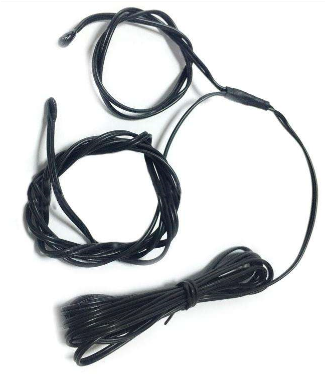
For families with children, I believe everyone knows more or less about Baby Sleeping Monitors. The common Baby Sleeping Monitors on the market can send an alarm signal after the baby kicks off the quilt to remind parents to put the quilt on the baby in time. Prevent babies from catching cold and cause fever and colds.
Baby Sleeping Monitors are composed of structure: host (indicator, power switch, alarm film and somatosensory clothing socket inside), receiving clothing and somatosensory clothing (connected to the somatosensory clothing socket with a plug wire). Among them, NTC thermistor, which plays a key role, is connected in series on the underwear of the body-sensitive clothing, front, back, upper and lower parts.
Working principle of Baby Sleeping Monitors: Utilizing the characteristic that the resistance value of NTC thermistor decreases with increasing temperature, an alarm will be issued to remind parents in time when the baby kicks off the quilt and the body feels cold. On the contrary, if the infants and young children wear too much or the quilt is too thick, and the body temperature rises, an alarm will be issued to notify the parents to avoid overheating.
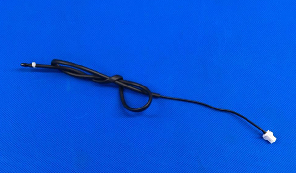
Our company specializes in the research, development and production of NTC thermistors and temperature sensors for nearly 12 years. The following small leather wire NTC thermistors can be used in Baby Sleeping Monitors.